22 Mar 2014
30 Dec 2012


Wireless Cable, HDTV, Cable Telephony, Interactive Television
Some of the future enhancements for CATV include wireless cable, cable
telephony, video on demand (VOD), and interactive television.
Wireless Cable
“Wireless Cable” is a term given to land based (terrestrial) wireless distribution systems that utilize microwave frequencies to deliver video, data, and/or voice signals to end-users. There are two basic types of wireless cable systems, multichannel multipoint distribution service (MMDS) and local multichannel distribution service (LMDS).
Multichannel video and data services are being offered over microwave frequencies. The data-over-cable service interface specification (DOCSIS) with a few modifications can also be used in 2.6 GHz wireless multipoint, multichannel distribution service (MMDS), and 28 GHz local multipoint distribution service (LMDS) systems [14]. The DOCSIS specification is being adapted for the wireless cable marketplace. A consortium called “Wireless DSL” is working to produce an adapted version of DOCSIS called DOCSIS+ that is suitable for offering cable modem technology via microwave transmission. The DOCSIS+ standard has been proposed to the IEEE 802.16 for conversion into an official standard.
Figure 1 shows a LMDS system. This diagram shows that the major component of a wireless cable system is the head-end equipment. The head-end equipment is equivalent to a telephone central office. The head-end building has a satellite connection for cable channels and video players for video on demand. The head-end is linked to base stations (BS) which transmits radio frequency signals for reception. An antenna and receiver in the home converts the microwave radio signals into the standard television channels for use in the home. As in traditional cable systems, a set-top box decodes the signal for input to the television. Low frequency wireless cable systems such as MMDS wireless cable systems (approx 2.5 GHz) can reach up to approximately 70 miles. High frequency LMDS systems (approx 28 GHz) can only reach approximately 5 miles.

Figure 1: Local Multipoint Distribution System (LMDS)
High Definition Television (HDTV)
High definition television (HDTV) is a TV broadcast system that proves higher picture resolution (detail and fidelity) than is provided by conventional NTSC and PAL television signals. HDTV signals can be in analog or digital form.
The specifications for HDTV digital systems allow for many types of data services in addition to digital video service. Digital HDTV channels carry high-speed digital services that can be addressed to a specific customer or group of customers that are capable of decoding and using those services. Examples of these services include: special programming information, software delivery, video or audio delivery (like pay-per-view programming), and instructional materials.
The data rate available for additional services is dynamic and ranges from a few kbps to several Mbps, depending on the video and audio program content. The gross data rate of the HDTV system is 19 Mbps. The amount of this data rate that is used by the HDTV video signal depends on the compression technology. Video data compression produces a data rate that changes dependent on the original video signal. When the video program contains rapidly changing scenes, most of the 19 Mbps signal is required for transmission. If the video signal is not changing rapidly, much of the 19 Mbps can be used for other types of services.
Transmission of the additional services has a lower priority than transmission of the primary program. If the primary service (HDTV) consumes a large part of the data (such as a rapidly changing video action scene), the customer may have to wait for some time prior to receiving large blocks of data.
Cable Telephony
Cable telephony is the providing of telephone services that use CATV systems to initiate, process, and receive voice communications. Cable telephony systems can either integrate telephony systems with cable modem networks (a teleservice) or the cable modem system can simply act as a transfer method for Internet telephony (bearer service). Because of government regulations (restrictions or high operational level requirements) in many countries, some cable operators are delaying the integration of telephone services with cable network. In either case, cable telephony systems are data telephony systems that include a voice gateway, gatekeeper, and a media interface.
Voice gateway is a network device that converts communication signals between data networks and telephone networks. A gatekeeper is a server that translates dialed digits into routing points within the cable network or to identify a forwarding number for the public telephone network. A multimedia transfer adapter converts multiple types of input signals into a common communications format.
Figure 2 shows a CATV system that offers cable telephony services. This diagram shows that a two-way digital CATV system can be enhanced to offer cable telephony services by adding voice gateways to the cable network’s head-end CMTS system and media terminal adapters (MTAs) at the residence or business. The voice gateway connects and converts signals from the public telephone network into data signals that can be transported on the cable modem system. The CMTS system uses a portion of the cable modem signal (data channel) to communicate with the MTA. The MTA converts the telephony data signal to its analog audio component for connection to standard telephones. MTAs are sometimes called integrated access devices (IADs).

Because of the high data transmission capability of cable television systems, cable telephony system can provide video telephony service. Video telephony is a telecommunications service that provides customers with both audio and video signals between their communications devices.
Interactive Television
Interactive television is a combination of cable, television, multimedia, PCs, and network programming that allows dynamic control of media display using inputs from the end-user. Interactive television has three basic types: “pay-per-view” involving programs that are independently billed, “near video-on-demand” (NVOD) with groupings of a single film starting at staggered times, and “video-on-demand” (VOD), enabling request for a particular film to start at the exact time of choice. Interactive television offers interactive advertising, home shopping, home banking, e-mail, Internet access, and games.
Video on demand (VOD) is a service that allows customers to request and receive video services. These video services can be from previously stored media (entertainment movies or education videos) or have a live connection (sporting events in real time).
A limited form of VOD is called near video on demand (NVOD). Near video on demand is a video service that allows a customer to select from a limited number of broadcast video channels. These video channels are typically movie channels that have pre-designated schedule times. Unlike full VOD service, the customer is not able to alter the start or play time of these broadcast videos.
Pay per view (PPV) is a process that allows customers to request the viewing of movies through an unscrambling process. PPV movies are usually broadcasted to all customers in a cable television network. To prevent unauthorized viewing, each PPV channel has its own scrambling code. To provide a customer with a reasonable selection of movies, the same movie is broadcasted on different channels with start intervals that range from 15 to 60 minutes. To provider twenty PPV movies, approximately 80 to 160 television channels would be required.
Analog cable systems provide up to 800 MHz of bandwidth. Using 6 MHz wide video channels, this allows up to 120 analog video channels. By digitizing each 6 MHz channel and using compressed digital video (10:1 compression), this increases the capacity of a cable system to over 500 digital television channels.
Cable converter boxes, known as set-top boxes, have different reception and decoding capabilities. Set-top boxes are required to convert distributed signals into a format suitable for viewing. Set-top boxes also can coordinate access to video on demand channels.
Electronic programming guide (EPG) is an interface (portal) that allows a customer to preview and select from possible list of available content media. EPGs can vary from simple program selection to interactive filters that dynamically allow the user to filter through program guides by theme, time period, or other criteria.
Figure 3 shows a video on demand system. This diagram shows that multiple video players are available and these video players can be access by the end customer through the set-top box. When the customer browses through the available selection list, they can select the media to play.

Figure 3: Video on Demand (VOD)
Hypervideo is a video program delivery system that allows the embedding of links (hotspots) inside a streaming video signal. This allows the customer (or receiving device) to dynamically alter the presentation of streaming information. Examples of hypervideo could be pre-selection of preferred advertising types or interactive game shows.
Synchronized television (syncTV) is a video program delivery application that simultaneously transmits hypertext markup language (HTML) data that is synchronized with television programming. Synchronized television allows the simultaneous display of a video program along with additional information or graphics that may be provided by advertisers or other information providers
Wireless Cable
“Wireless Cable” is a term given to land based (terrestrial) wireless distribution systems that utilize microwave frequencies to deliver video, data, and/or voice signals to end-users. There are two basic types of wireless cable systems, multichannel multipoint distribution service (MMDS) and local multichannel distribution service (LMDS).
Multichannel video and data services are being offered over microwave frequencies. The data-over-cable service interface specification (DOCSIS) with a few modifications can also be used in 2.6 GHz wireless multipoint, multichannel distribution service (MMDS), and 28 GHz local multipoint distribution service (LMDS) systems [14]. The DOCSIS specification is being adapted for the wireless cable marketplace. A consortium called “Wireless DSL” is working to produce an adapted version of DOCSIS called DOCSIS+ that is suitable for offering cable modem technology via microwave transmission. The DOCSIS+ standard has been proposed to the IEEE 802.16 for conversion into an official standard.
Figure 1 shows a LMDS system. This diagram shows that the major component of a wireless cable system is the head-end equipment. The head-end equipment is equivalent to a telephone central office. The head-end building has a satellite connection for cable channels and video players for video on demand. The head-end is linked to base stations (BS) which transmits radio frequency signals for reception. An antenna and receiver in the home converts the microwave radio signals into the standard television channels for use in the home. As in traditional cable systems, a set-top box decodes the signal for input to the television. Low frequency wireless cable systems such as MMDS wireless cable systems (approx 2.5 GHz) can reach up to approximately 70 miles. High frequency LMDS systems (approx 28 GHz) can only reach approximately 5 miles.

Figure 1: Local Multipoint Distribution System (LMDS)
High Definition Television (HDTV)
High definition television (HDTV) is a TV broadcast system that proves higher picture resolution (detail and fidelity) than is provided by conventional NTSC and PAL television signals. HDTV signals can be in analog or digital form.
The specifications for HDTV digital systems allow for many types of data services in addition to digital video service. Digital HDTV channels carry high-speed digital services that can be addressed to a specific customer or group of customers that are capable of decoding and using those services. Examples of these services include: special programming information, software delivery, video or audio delivery (like pay-per-view programming), and instructional materials.
The data rate available for additional services is dynamic and ranges from a few kbps to several Mbps, depending on the video and audio program content. The gross data rate of the HDTV system is 19 Mbps. The amount of this data rate that is used by the HDTV video signal depends on the compression technology. Video data compression produces a data rate that changes dependent on the original video signal. When the video program contains rapidly changing scenes, most of the 19 Mbps signal is required for transmission. If the video signal is not changing rapidly, much of the 19 Mbps can be used for other types of services.
Transmission of the additional services has a lower priority than transmission of the primary program. If the primary service (HDTV) consumes a large part of the data (such as a rapidly changing video action scene), the customer may have to wait for some time prior to receiving large blocks of data.
Cable Telephony
Cable telephony is the providing of telephone services that use CATV systems to initiate, process, and receive voice communications. Cable telephony systems can either integrate telephony systems with cable modem networks (a teleservice) or the cable modem system can simply act as a transfer method for Internet telephony (bearer service). Because of government regulations (restrictions or high operational level requirements) in many countries, some cable operators are delaying the integration of telephone services with cable network. In either case, cable telephony systems are data telephony systems that include a voice gateway, gatekeeper, and a media interface.
Voice gateway is a network device that converts communication signals between data networks and telephone networks. A gatekeeper is a server that translates dialed digits into routing points within the cable network or to identify a forwarding number for the public telephone network. A multimedia transfer adapter converts multiple types of input signals into a common communications format.
Figure 2 shows a CATV system that offers cable telephony services. This diagram shows that a two-way digital CATV system can be enhanced to offer cable telephony services by adding voice gateways to the cable network’s head-end CMTS system and media terminal adapters (MTAs) at the residence or business. The voice gateway connects and converts signals from the public telephone network into data signals that can be transported on the cable modem system. The CMTS system uses a portion of the cable modem signal (data channel) to communicate with the MTA. The MTA converts the telephony data signal to its analog audio component for connection to standard telephones. MTAs are sometimes called integrated access devices (IADs).

Figure 2: Cable Telephony
Because of the high data transmission capability of cable television systems, cable telephony system can provide video telephony service. Video telephony is a telecommunications service that provides customers with both audio and video signals between their communications devices.
Interactive Television
Interactive television is a combination of cable, television, multimedia, PCs, and network programming that allows dynamic control of media display using inputs from the end-user. Interactive television has three basic types: “pay-per-view” involving programs that are independently billed, “near video-on-demand” (NVOD) with groupings of a single film starting at staggered times, and “video-on-demand” (VOD), enabling request for a particular film to start at the exact time of choice. Interactive television offers interactive advertising, home shopping, home banking, e-mail, Internet access, and games.
Video on demand (VOD) is a service that allows customers to request and receive video services. These video services can be from previously stored media (entertainment movies or education videos) or have a live connection (sporting events in real time).
A limited form of VOD is called near video on demand (NVOD). Near video on demand is a video service that allows a customer to select from a limited number of broadcast video channels. These video channels are typically movie channels that have pre-designated schedule times. Unlike full VOD service, the customer is not able to alter the start or play time of these broadcast videos.
Pay per view (PPV) is a process that allows customers to request the viewing of movies through an unscrambling process. PPV movies are usually broadcasted to all customers in a cable television network. To prevent unauthorized viewing, each PPV channel has its own scrambling code. To provide a customer with a reasonable selection of movies, the same movie is broadcasted on different channels with start intervals that range from 15 to 60 minutes. To provider twenty PPV movies, approximately 80 to 160 television channels would be required.
Analog cable systems provide up to 800 MHz of bandwidth. Using 6 MHz wide video channels, this allows up to 120 analog video channels. By digitizing each 6 MHz channel and using compressed digital video (10:1 compression), this increases the capacity of a cable system to over 500 digital television channels.
Cable converter boxes, known as set-top boxes, have different reception and decoding capabilities. Set-top boxes are required to convert distributed signals into a format suitable for viewing. Set-top boxes also can coordinate access to video on demand channels.
Electronic programming guide (EPG) is an interface (portal) that allows a customer to preview and select from possible list of available content media. EPGs can vary from simple program selection to interactive filters that dynamically allow the user to filter through program guides by theme, time period, or other criteria.
Figure 3 shows a video on demand system. This diagram shows that multiple video players are available and these video players can be access by the end customer through the set-top box. When the customer browses through the available selection list, they can select the media to play.

Figure 3: Video on Demand (VOD)
Hypervideo is a video program delivery system that allows the embedding of links (hotspots) inside a streaming video signal. This allows the customer (or receiving device) to dynamically alter the presentation of streaming information. Examples of hypervideo could be pre-selection of preferred advertising types or interactive game shows.
Synchronized television (syncTV) is a video program delivery application that simultaneously transmits hypertext markup language (HTML) data that is synchronized with television programming. Synchronized television allows the simultaneous display of a video program along with additional information or graphics that may be provided by advertisers or other information providers
Digital Video
Digital broadcasting is the sending of a digital signal through a common
channel to a group of users that may be capable of decoding some or all of the broadcast
information.
Digital Television (DTV) is a method of transferring video images and their audio components through digital transmission. There are several formats used for DTV including high quality digital MPEG and 28.8 video.
Digital video is the sending of a sequence of picture signals (frames) that are represented by binary data (bits) that describe a finite set of color and luminance levels. Sending a digital video picture involves the conversion of a scanned image to digital information that is transferred to a digital video receiver. The digital information contains characteristics of the video signal and the position of the image (bit location) that will be displayed. Digital television continues to send information in the form of frames and pixels. The major difference is the frames and pixels are represented by digital information instead of a continuously varying analog signal.
The first digital television broadcast license for the United States was issued to a Hawaiian television station in September 1997. Digital television sends the video signal in digital modulated form. Ironically, many television signals have been captured and stored in digital form for over 10 years. To transmit these digital video signals, they must first be converted to standard analog television (NTSC or PAL) to be transmitted through analog transmission systems and to reach analog televisions.
When digital transmission is used, most digital video systems use some form of data compression. Data compression involves the characterization of a single picture into its components. For example, if the picture was a view of the blue sky, this could be characterized by a small number of data bits that indicate the color (blue) and the starting corner and ending corner. This may require under 10 bytes of information. When this digital information is received, it will create a blue box that may contain over 7,200 pixels. With a color picture, this would have required several thousand bytes of information for only 1 picture.
In addition to the data compression used on one picture (one frame), digital compression allows the comparison between frames. This allows the repeating of sections of a previous frame. For example, a single frame may be a picture of city with many buildings. This is a very complex picture and data compression will not be able to be as efficient as the blue sky example above. However, the next frame will be another picture of the city with only a few changes. The data compression can send only the data that has changed between frames.
Digital television broadcasting that uses video compression technology allows for “multicasting” (simultaneously sending) several “standard definition” television channels (normally up to five channels) in the same bandwidth as a standard analog television channel. Unfortunately, high definition digital television channels require a much higher data transmission rate and it is likely that only a single HDTV channel can be sent on a digital television channel.
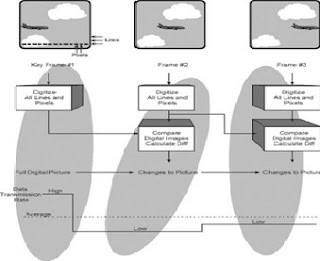
Figure 1 demonstrates the operation of the basic digital video compression system. Each video frame is digitized and then sent for digital compression. The digital compression process creates a sequence frames (images) that start with a key frame. The key frame is digitized and used as reference points for the compression process. Between the key frames, only the differences in images are transmitted. This dramatically reduces the data transmission rate to represent a digital video signal as an uncompressed digital video signal requires over 50 Mbps compared to less than 4 Mbps for a typical digital video disk (DVD) digital video signal.
Digital Television (DTV) is a method of transferring video images and their audio components through digital transmission. There are several formats used for DTV including high quality digital MPEG and 28.8 video.
Digital video is the sending of a sequence of picture signals (frames) that are represented by binary data (bits) that describe a finite set of color and luminance levels. Sending a digital video picture involves the conversion of a scanned image to digital information that is transferred to a digital video receiver. The digital information contains characteristics of the video signal and the position of the image (bit location) that will be displayed. Digital television continues to send information in the form of frames and pixels. The major difference is the frames and pixels are represented by digital information instead of a continuously varying analog signal.
The first digital television broadcast license for the United States was issued to a Hawaiian television station in September 1997. Digital television sends the video signal in digital modulated form. Ironically, many television signals have been captured and stored in digital form for over 10 years. To transmit these digital video signals, they must first be converted to standard analog television (NTSC or PAL) to be transmitted through analog transmission systems and to reach analog televisions.
When digital transmission is used, most digital video systems use some form of data compression. Data compression involves the characterization of a single picture into its components. For example, if the picture was a view of the blue sky, this could be characterized by a small number of data bits that indicate the color (blue) and the starting corner and ending corner. This may require under 10 bytes of information. When this digital information is received, it will create a blue box that may contain over 7,200 pixels. With a color picture, this would have required several thousand bytes of information for only 1 picture.
In addition to the data compression used on one picture (one frame), digital compression allows the comparison between frames. This allows the repeating of sections of a previous frame. For example, a single frame may be a picture of city with many buildings. This is a very complex picture and data compression will not be able to be as efficient as the blue sky example above. However, the next frame will be another picture of the city with only a few changes. The data compression can send only the data that has changed between frames.
Digital television broadcasting that uses video compression technology allows for “multicasting” (simultaneously sending) several “standard definition” television channels (normally up to five channels) in the same bandwidth as a standard analog television channel. Unfortunately, high definition digital television channels require a much higher data transmission rate and it is likely that only a single HDTV channel can be sent on a digital television channel.
Figure 1 demonstrates the operation of the basic digital video compression system. Each video frame is digitized and then sent for digital compression. The digital compression process creates a sequence frames (images) that start with a key frame. The key frame is digitized and used as reference points for the compression process. Between the key frames, only the differences in images are transmitted. This dramatically reduces the data transmission rate to represent a digital video signal as an uncompressed digital video signal requires over 50 Mbps compared to less than 4 Mbps for a typical digital video disk (DVD) digital video signal.

Technologies- Analog Video
Some of the key technologies used in CATV systems include analog video.
Analog Video
Analog video contains a rapidly changing signal (analog) that represents cthe luminance and color information of a video picture. Sending a video picture involves the creation and transfer of a sequence of individual still pictures called frames. Each frame is divided into horizontal and vertical lines. To create a single frame picture on a television set, the frame is drawn line by line. The process of drawing these lines on the screen is called scanning. The frames are drawn to the screen in two separate scans. The first scan draws half of the picture and the second scan draws between the lines of the first scan. This scanning method is called interlacing. Each line is divided into pixels that are the smallest possible parts of the picture. The number of pixels that can be displayed determines the resolution (quality) of the video signal. The video signal breaks down the television picture into three parts: the picture brightness (luminance), the color (chrominance), and the audio.
There are three primary systems used for analog television broadcasting: NTSC, PAL, and SECAM. The National Television System Committee (NTSC) is used for the Americas, while PAL and SECAM are primarily used in the UK and other countries. The major difference between the analog television systems is the number of lines of resolution and the methods used for color transmission.
There have been enhancements made to analog video systems over the past 50 years. These include color video, stereo audio, separate audio programming channels, slow data rate digital transfer (for closed captioning), and ghost canceling. The next major change to television technology will be its conversion to HDTV.
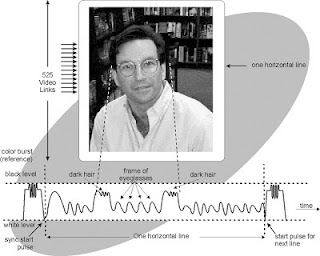
Figure 1 demonstrates the operation of the basic NTSC analog television system. The video source is broken into 30 frames per second and converted into multiple lines per frame. Each video line transmission begins with a burst pulse (called a sync pulse) that is followed by a signal that represents color and intensity. The time relative to the starting sync is the position on the line from left to right. Each line is sent until a frame is complete and the next frame can begin. The television receiver decodes the video signal to position and control the intensity of an electronic beam that scans the phosphorus tube (“picture tube”) to recreate the display.
Analog Video
Analog video contains a rapidly changing signal (analog) that represents cthe luminance and color information of a video picture. Sending a video picture involves the creation and transfer of a sequence of individual still pictures called frames. Each frame is divided into horizontal and vertical lines. To create a single frame picture on a television set, the frame is drawn line by line. The process of drawing these lines on the screen is called scanning. The frames are drawn to the screen in two separate scans. The first scan draws half of the picture and the second scan draws between the lines of the first scan. This scanning method is called interlacing. Each line is divided into pixels that are the smallest possible parts of the picture. The number of pixels that can be displayed determines the resolution (quality) of the video signal. The video signal breaks down the television picture into three parts: the picture brightness (luminance), the color (chrominance), and the audio.
There are three primary systems used for analog television broadcasting: NTSC, PAL, and SECAM. The National Television System Committee (NTSC) is used for the Americas, while PAL and SECAM are primarily used in the UK and other countries. The major difference between the analog television systems is the number of lines of resolution and the methods used for color transmission.
There have been enhancements made to analog video systems over the past 50 years. These include color video, stereo audio, separate audio programming channels, slow data rate digital transfer (for closed captioning), and ghost canceling. The next major change to television technology will be its conversion to HDTV.
Figure 1 demonstrates the operation of the basic NTSC analog television system. The video source is broken into 30 frames per second and converted into multiple lines per frame. Each video line transmission begins with a burst pulse (called a sync pulse) that is followed by a signal that represents color and intensity. The time relative to the starting sync is the position on the line from left to right. Each line is sent until a frame is complete and the next frame can begin. The television receiver decodes the video signal to position and control the intensity of an electronic beam that scans the phosphorus tube (“picture tube”) to recreate the display.

Simple Telecom Technologies
Telecommunication transmission technology is often lumped into two
categories: analog transmission or digital transmission. Figure 4.1 depicts a
basic telecommunications transmission system that transfers digital information
from one source to an information receiver. The information source is supplied
to an end-node that converts the information to a form that can be transmitted
through the transmission medium (air, copper, or fiber). The receiving end-node
converts the transmission signal into a form that is compatible for the
receiver of the information.

Analog
Analog transmission is a process of transferring signals between end-nodes than can have many different signal levels and frequencies. Because analog signals can continuously change to many different levels (voltages) at changing rates (frequencies), the transfer of analog signals (such as an audio signal) requires the transmission medium to have similar transfer characteristics to all parts (levels and frequencies) of the transmission signal. Analog transmission systems must be robust to transfer the signal unaltered for specific voltage levels and frequency components (e.g., high and low frequency).
Figure below shows an analog transmission system. This diagram shows that an audio acoustic (sound) signal is converted by a microphone to an audio electrical signal prior to transmission on a copper line. This audio electrical signal is amplified by an end-node to increase the signal level for transmission on a copper wire. This amplification is necessary to overcome the transmission loss of the copper wire. As the signal progresses down the copper wire, some of the signal energy is converted to heat reducing the signal level. Another amplifier (the receiving end-node) is located at the receiving end to increase the signal to a level suitable for the information receiver (audio speaker).

Digital
Digital transmission is the process of transferring information from node to node in a form that can only have specific levels (usually logic 1 and logic 0). Digital signals have a limited number of different levels (voltages) that represent digital information. Transferring digital signals (such as a computer’s data signal) only requires the transmission medium to transfer two levels without precisely (linearly) transferring levels in between the two levels.
Figure below shows a digital transmission system. This diagram shows a computer that is sending digital data (one equal to +5 volts and zero equal to 0 volts) to an end-node. The end-node is a channel service unit (CSU) and digital service unit (DSU) that converts the levels from the computer to levels suitable for the copper wire transmission medium (logic 1 = +5V and logic 0 = -5V). As the digital signal transfers down the copper wire, some of the energy is converted to heat and some of the frequency components are attenuated resulting in a slightly distorted (rounded) digital pulse arriving at the receiving end-node. Because the receiving CSU/DSU only needs to sense two levels, it is able to re-create the original undistorted digital signal (also known as digital signal regeneration).


Basic Transmission System
Analog
Analog transmission is a process of transferring signals between end-nodes than can have many different signal levels and frequencies. Because analog signals can continuously change to many different levels (voltages) at changing rates (frequencies), the transfer of analog signals (such as an audio signal) requires the transmission medium to have similar transfer characteristics to all parts (levels and frequencies) of the transmission signal. Analog transmission systems must be robust to transfer the signal unaltered for specific voltage levels and frequency components (e.g., high and low frequency).
Figure below shows an analog transmission system. This diagram shows that an audio acoustic (sound) signal is converted by a microphone to an audio electrical signal prior to transmission on a copper line. This audio electrical signal is amplified by an end-node to increase the signal level for transmission on a copper wire. This amplification is necessary to overcome the transmission loss of the copper wire. As the signal progresses down the copper wire, some of the signal energy is converted to heat reducing the signal level. Another amplifier (the receiving end-node) is located at the receiving end to increase the signal to a level suitable for the information receiver (audio speaker).

Analog Transmission System
Digital
Digital transmission is the process of transferring information from node to node in a form that can only have specific levels (usually logic 1 and logic 0). Digital signals have a limited number of different levels (voltages) that represent digital information. Transferring digital signals (such as a computer’s data signal) only requires the transmission medium to transfer two levels without precisely (linearly) transferring levels in between the two levels.
Figure below shows a digital transmission system. This diagram shows a computer that is sending digital data (one equal to +5 volts and zero equal to 0 volts) to an end-node. The end-node is a channel service unit (CSU) and digital service unit (DSU) that converts the levels from the computer to levels suitable for the copper wire transmission medium (logic 1 = +5V and logic 0 = -5V). As the digital signal transfers down the copper wire, some of the energy is converted to heat and some of the frequency components are attenuated resulting in a slightly distorted (rounded) digital pulse arriving at the receiving end-node. Because the receiving CSU/DSU only needs to sense two levels, it is able to re-create the original undistorted digital signal (also known as digital signal regeneration).

Digital
Transmission System
Subscribe to:
Comments (Atom)